
Water Turbine Design
Water Turbine Design for Small Scale Hydro Energy
![]() Hydro schemes use various types of water turbine design to produce a rotary turning action at a medium to high rotational speed. Also water turbines, or more specifically hydro turbines, can be used as part of a home hydro electricity system by installing an electrical generator.
Hydro schemes use various types of water turbine design to produce a rotary turning action at a medium to high rotational speed. Also water turbines, or more specifically hydro turbines, can be used as part of a home hydro electricity system by installing an electrical generator.
Unlike a water pump which is mechanically driven by an electric motor or wind turbine and uses suction to pump the water through it, a typical water turbine design uses nozzles and differential water pressure to produce a mechanical rotation and output.
In other words, a water turbine converts water pressure energy into mechanical energy. It is important at this point to understand the difference between a Water Turbine Design and a waterwheel design which we look at in the previous tutorial.
A waterwheel is a simple but large circular wooden or metallic wheel with buckets attached around its periphery that slowly turns as the flow of water pours over or underneath it producing lots of mechanical torque to drive auxiliary machinery. A water turbine on the other hand, is a much smaller, lightweight cast iron or steel machine in which the kinetic energy of the water is converted into mechanical energy through the use of correctly placed pressure nozzles.

The water turbine is the heart of any hydro power plant. It consists of a number of metal or plastic blades fitted to a central rotating shaft or plate. Water flowing through the casing of the enclosed turbine, strikes the blades of the turbine producing torque and making the shaft rotate due to the velocity and pressure of the water. As the water pushes against the turbine blades, its velocity and pressure reduces (energy is lost) as it rotates the turbine shaft.
However, as a typical “water turbine design” has lots more blades attached to this central shaft, this rotation causes the next blade behind it to come into contact with the entering water pressure causing the turbine to rotate some more and so on.
As the turbine continues to rotate, the water becomes trapped in between the turbines blades and is pushed along by the rotational movement of the turbine. At some point along the rotational angle of the turbine blades, the water encounters an opening in the casing, usually located at the center, which allows the water to exit and return back to the river or stream from where it originally came.
This waste water can pass through the body of a water turbine using different flow paths and based upon the actual path of water flow through the turbine, modern water turbine designs can be categorised as being either:
- Axial Flow Turbines – The water flow path through an axial flow water turbine design is parallel to the axis of rotation as it enters the turbines wheel from the side.
- Radial Flow Turbines – The water flows path through a radial flow water turbine design is perpendicular to the axis of rotation of the turbine as it enters the turbines wheel from above.
There are many different water turbine designs in use today, with each type having its own advantages and disadvantages depending upon their operational requirements. The selection of the correct type of water turbine design is very important for the success of any small or large scale hydro power system.
The optimum mechanical power output from the turbines rotating shaft relies on a specific combination of head height, water volume and water pressure entering the turbines blades, which can only be achieved by selecting the correct type of water turbine for a given installation. Then based upon the actual change in the waters pressure as it used by the turbines wheel, modern water turbine designs can be categorised as either:
- Reaction Turbine Design – in this type of water turbine design, the turbine blades are totally submersed in the flow of the water and are enclosed within a pressurised casing. A reaction turbine is powered mainly by the change in pressure, called a “pressure drop” across the casings body as this reduction in water pressure and velocity releases energy causing a reaction (hence the name) by moving the turbines blades. The flow of water through a reaction turbine may be reversed due to the angle of the internal blades, so a reaction turbine can also be used to pump water and vice versa.
- Impulse Turbine Design – in this type of water turbine design, the water flow hits the turbine blades from one or more jets of water known as nozzles. These nozzles convert the pressurised low velocity water into a high speed jet of water aimed directly at the turbines curved spoon or bucket shaped blades generating maximum force on the blades. The mechanical power output from an impulse turbine is derived from the kinetic energy of the water flow. An impulse turbine operates in a fully-open or semi-open casing therefore there is no pressure drop across and impulse turbine and due to its open nozzle jet design it can not be reversed.
Types of Water Turbine Design
As well as the type of operation of a water turbine, water turbines are often referred to by the design, structure and layout of their blades inside the actual turbine body. Names such as: “Pelton Turbines”, “Turgo Turbines” or “Kaplan Turbines” all refer to the name of the designer and/or inventor of that particular water turbine design. Following are some of the more common types of water turbine designs. But before we look at the different types of water turbines available, we first need to understand some of the “jargon” associated with water turbines.
The word Head is the term used in hydro energy applications to define the vertical distance the water must fall from a higher elevation to a lower point in order to release its stored potential energy. The difference between these two elevations (the higher minus the lower) is called the “head” of the system.
Generally, in hydro energy and hydro-electric power systems, a low-head means a vertical distance of less than 100 feet (approx 30 metres), a medium-head means a vertical distance of between 100 to 500 feet (30-to-150 metres), while a high-head means a vertical distance greater than 500 feet, (150 metres).
The amount of head available in hydro energy system determines the amount of power available from the water as Power is proportional to Head x Flow. The flow of water through the turbine is normally expressed in litres per second, (ltr/s) or cubic metres per second (m3/s) and refers to the quantity or volume of water used by the turbine to turn the shaft.
Pelton Water Turbine Design
Pelton Turbine Design

A Pelton Water Turbine also known as a Pelton Wheel, and named after its inventor Lester Pelton, is the most common open type turbine wheel design available. The Pelton is an impulse type circular turbine in which the circumference of the wheels outer rim is surrounded by a series of equally spaced small curved cups or buckets that catch the water.
The water’s energy is delivered to these spoon shaped cups at a high pressure and velocity through one or more nozzles arranged around the circumference of the wheel. Each nozzle produces a jet of water which is aimed directly at the individual cups.
These spoon shaped cups are formed into two halves so that when the jet of water hits the middle of each cup in turn, the quantity of water splits in half. Each half of the water flows around the its own curved shape of the cup by almost 180o and is deflected back out in the direction from where it came causing a pushing force against the cup.
Then the potential energy generated by the water jet is converted into kinetic energy through these nozzles and nearly all of the energy of the moving water goes into propelling the cups. The jets of water from the nozzles push against the cups of the turbine making the wheel rotate, producing torque and power.
Depending upon the available water head and number of nozzles positioned tangentially around the wheel, the velocity and direction of the jets of water coming from these nozzles can be controlled to allowing for a constant slower speed which is ideal for electrical power generation. Then the speed of a Pelton turbine can be controlled by adjusting the flow of water to the cups or buckets through the nozzles.
The Pelton turbine is a free flow action that runs in atmospheric air as jets of water leave the nozzles are at high velocity but at atmospheric pressure. The waste water also leave the cups at atmospheric pressure making it an impulse turbine, as there is no pressure drop across the turbine. In a Pelton Turbine Design, the angular velocity of the cups is at just under half the velocity of the jet(s). Thus, this type of water turbine design is high speed and smooth running so is better suited to high head, low water volume conditions.
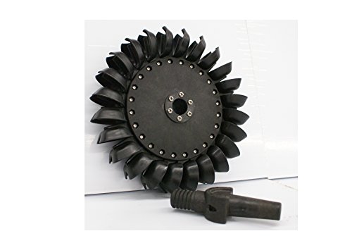
Turgo Water Turbine Design
Turgo Turbine Design

The Turgo Water Turbine, is another impulse type water turbine design in which a jet of water strikes the turbines blades. The turgo turbine design is similar to the previous Pelton wheel but this time the water jet from the nozzle strikes a series of curved or angled blades instead of cups or buckets from the side at a shallow angle of about 20o instead of tangentially so that the water hits the angled blade from one side and exits on the other. These curved blades catch the water as it flows through the turbine causing the turbines shaft to rotate.
As the flow of the water through the turbines wheel enters at one angle and exits at another, the flow of the incoming jet of water is not hindered by the exiting waste water, as is the case with Pelton turbines, allowing for a higher flow rate. Also due to this higher flow rate, a Turgo turbine can have a much smaller diameter wheel than an equivalent Pelton for the same amount of power output allowing them to rotate at higher speeds. However, the Turgo wheel is less efficient than the previous Pelton wheel.
Francis Water Turbine Design
Francis Turbine Design

The Francis Water Turbine, named after its inventor James Francis, is a radial flow reaction type of water turbine design in which the entire turbine wheel assembly is immersed in water and surrounded by a pressurised spiral casing. Water enters the casing under pressure and is guided through a set of fixed or adjustable slots called guide vanes around the casing which direct the flow of water to the turbines blades at the correct angle.
The water impacts against a set of curved turbine blades mounted on a shaft and glides over them thereby changing direction and producing pressure on the fixed blades due to centrifugal force causing it to rotate. The water enters the turbines blades radially nearly at a tangent but to increase efficiency, the water changes direction inside the turbines wheel and exits in parallel (axially) with the axis of rotation at a reduced velocity.
A Francis turbine is a submerged turbine similar in design to a propeller turbine that uses water pressure and kinetic energy to rotate the blades. The energy from the flow of the water is transferred to the output shaft of the turbine in form of torque and rotation. The turbines internal blades are fixed and cannot be adjusted so to maintain a constant turbine speed, the water flow rate is adjusted by changing the angle of the casings guide vanes.
The Francis Turbine is suitable for low to medium head applications but requires a relatively large quantity of water. Depending upon its application, the turbine shaft of a Francis turbine can be mounted horizontal or vertical.
Kaplan Water Turbine Design
Kaplan Turbine Design

The Kaplan Water Turbine, named after its Austrian inventor Victor Kaplan, is an axial flow reaction type of water turbine that looks very similar to a ships propeller. As a result, the Kaplan Turbine is also referred to as a Propeller Turbine.
The Kaplan’s propeller shaped rotor has two or more fixed or adjustable blades. Similar to the previous Francis Turbine, the Kaplan Turbine can also has a set of fixed or adjustable guide vanes around the inlet of the turbine to control its rotational speed.
The operation of a Kaplan turbine is the reverse to that of a ships propeller. The water enters the turbine passage in a radial direction via the inlet vanes. The angle and position of these vanes causes the water to swirl producing a vortex within the enclosed passage applying a force onto the angular shaped propeller blades. As the propellers twisted rotor blades are fixed within this passage to a central shaft, the force of the swirling water pushing against the blades transfers energy to the blades producing a rotation and torque.
One of the major advantages of the Kaplan turbine, is that they can be used in very low head applications, providing that there is sufficiently large water flow rates through the turbine, without the need for dams and weirs resulting in a negligible impact on the environment.
Also depending on the amount or variability in the amount of water flowing through the turbine, the pitch (angle of attack) of the propeller blades can be adjusted allowing for greater control of the water flow and increasing efficiency. However, adjustable propeller blades add to the complexity of the construction of a Kaplan turbine design.
Cross Flow Water Turbine Design
Cross-flow Turbine Design

The Cross Flow Water Turbine, also known as a Michell-Banki turbine, after its manufacturer, is another impulse type water turbine design in which the water strikes the turbines blades transversely across its blades.
Cross-flow turbines use a cylindrical drum shaped rotor, similar to the waterwheel of an old style paddle wheeled steamboat, that has a number of blades or slats called runners, installed lengthwise around the rotors circumference depending upon the size of the turbine wheel, which may be up to two metres in diameter.
The water is fed to these slats through a single or double vertical rectangular nozzle to drive a jet of water along the full length of the runner. These nozzles direct the water to the runners at the optimal angle causing them to move converting the potential energy of the water to kinetic energy.
After hitting the first blade and expending its energy, the water drops down through the drum and leaves on the opposite side. Then the cross-flow turbine uses the energy of the water twice, once from above and once from below to rotate the turbine wheel around its central axis providing additional efficiency.

The main advantage of the cross-flow turbine is that it maintains its efficiency under varying load and water flow conditions. Also due to their relatively easy construction, good regulation, and can operate with a very low head of water, cross-flow water turbines are ideal for use in mini and micro hydro-power systems.
Selecting the Best Type of Water Turbine Design
Selecting the best type of water turbine design for your particular situation often depends on the amount of head and flow rate that is available at your particular location and whether it is at the side of a river or stream, or the water is to be channeled or piped directly to your location.
Other factors include whether you want an enclosed “reaction turbine design” such as the Francis turbine or an open “impulse turbine design”, such as the Pelton turbine as well as the speed of rotation of your proposed electrical generator.
By analysing all of these factors together you can get some indication of what type of Water Turbine Design may work best for your particular situation. Knowing the difference between a Pelton and Francis turbine for example, will help make the choice easier.
The following table gives a basic idea of which particular Water Turbine Design we have discussed above works best according to the available head height and water pressure.
Turbine Design against Head Pressure
| Water Turbine Type | Head Water Pressure | ||
| High → | Medium → | Low | |
| Impulse Type Water Turbine Design | Multi-jet Pelton, Turgo | Pelton, Turgo, Cross flow | Cross flow |
| Reaction Type Water Turbine Design | Francis | Francis, Kaplan | Kaplan |
We can see from the table above that there is an overlap between Pelton and Cross-flow turbines, and again between Francis and Kaplan turbines. This means, that both types of turbines are suitable for such combinations of head height and flow.
An alternative to the different types of water turbines detailed above, is the use of standard water pumps as water turbines. The inverse use of water pumps as water turbines for small hydroelectric power plants has become a popular alternative to the more expensive water turbines due to their availability and cheap cost.
Unfortunately using water pumps as water turbines has a few disadvantages such as, their efficiency is greatly reduced compared to turbines using the same head height, and that pumps used as turbines are more sensitive to cavitation and operating range.
The main difference between the operation of a pump as a turbine is that the water flowing to the pump is determined by the head height, of which there is not control, while a water turbine has flow control through the nozzles and blades, which is one of the reasons for its higher cost.
One final thought, If the water turbine is to be used with and electrical generator to convert the turbines mechanical energy into electrical energy, a gearbox or pulley system may be required as the rotational speed of the turbine may be too low compared to the rotational speed required by the generator.
In the next Hydro Energy Tutorial, we will look at micro-hydro power systems used to generate hydroelectricity. For more information about Water Turbine Design and how to generate your own electricity using the power of water, or to obtain more hydro energy information about the various turbine designs available, or to explore the advantages and disadvantages of hydro energy, then why not Click Here to order your copy from Amazon today about how to build a water turbine generator and other types of Water Turbine Designs.


very good and informative article on design of water turbine. kindly provide pdf of this article at the end of the article. thank you
can you send me a magazine with prices of your product like water turbine
We do not have a magazine with prices of products like water turbine
Kindly give the cost 30KWT Turgo Water Turbine high speed design
We are required the beloPelton Turbine Range: 8-10” diameter, body should be made of cast iron,95% efficiency, 500W with complete gear box, pulley, coupling bearings, and other necessary accessories. w mentioned items quotation, delivery duration and shipment cost on urgent basis.
Thank you so much!
Hi there
Thanks for the article. I am wondering if there are any turbines under 3 inches in diameter? And if so, how much energy does it generate? Thanks!
Ah, just realised its a water turbine you need. Yes 3 inch (75mm) for micro-hydro systems are available. The amount of energy it generates depends on maximum water flow, number of nozzles and net head (the energy in the water). The type of generator used will also make a difference.
we have treatment water unit and products about 14 cubic meter every hour and reject about 29 cubic meter every hour too,I intend to use this wast water to rotate water turbine until generate power to run the water unite to save power ” power recovery system” Could you give me some instruction to use this method soon?
If I have a water turbine that is for arguments sake 6″ in diameter and at a given flow rate rotates at 500 RPM, if I add a second 3″ diameter turbine to the opposite end of the shaft will the 6″ turbines RPM be reduced by 50% or to 250 RPM?
Note that the second turbine is facing the opposite direction to the 6″ turbine.
If you intend to run the two turbines of the same shaft, then the rotational speed would depend on the flow rate over both turbine blades as I would assume that both turbines are fed from two different water sources. One for the 6″ and one for the 3″. Thus the pressure head (H) and flow rate (Q) of each turbine can be adjusted to balance the rpm.
Hi there
Thanks for the article:)
I have been looking for a turbine like the ones there is on watering machines with self reel in. on these turbines the water pressure drives the turbine and the turbine drives the reel in mechanism. I found NOTHING – Maybe you guys can point me in the right direction?
Thank you in advance.