
Bypass Diode for Solar Panel Protection
The Bypass Diode in Photovoltaic Panels
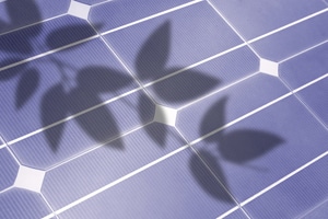
![]() A Bypass Diode is used in solar photovoltaic (PV) arrays to protect partially shaded PV cells from fully operating cells in full sun within the same solar panel when used in high voltage series arrays.
A Bypass Diode is used in solar photovoltaic (PV) arrays to protect partially shaded PV cells from fully operating cells in full sun within the same solar panel when used in high voltage series arrays.
Solar photovoltaic panel are a great way to generate free electrical energy using the power of the sun. You just place them wherever you want and away you go either as part of an off-grid stand alone system or as roof installed PV panels for a grid connected system. The power range of a solar photovoltaic system is extremely wide, from a few milliwatts to hundreds of megawatts due in part to the modularity of the solar panels.

Photovoltaic cells are a type of semiconductor photodiode that directly converts the light hitting their surface into electrical power. PV systems generate electricity by connecting solar photovoltaic panels together in the form of an array and exposing them to the direct sunlight.
We would think then that during normal operation all the solar panels of a PV system would experience the same solar conditions as they all form part of the same solar array.
However, the electrical generating performance and reliability of a PV system can be affected by external factors, such as environment, temperature, humidity, positioning, and degree of solar radiation which can all lead to power degradation.
But as well as these obvious environmental factors, one factor in particular that will lead to mismatches between solar cells or whole panels, and power degradation within a solar array is shading, that is the blocking of the sunlight onto the cell, or panel by leaves, trees, buildings or antennas. This can be either full or partial shading, and depending on the degree of shading, will cause a decrease of output power.
Series Connected Solar Cells
Photovoltaic (PV) panels are made from interconnected crystalline silicon cells and are therefore sensitive to shading. In a standard PV panel, these solar cells are connected together in series, result in high voltage but the same value of current flows through all the connected cells.
So as long as the sunlight hitting the surface of the PV panel is uniform, each photovoltaic cell within the same panel will produce the same amount of electrical voltage, approximately 0.5 volts. Then for instance, at full sun a 2 watt PV cell will produce a constant current of about 4 amperes, (0.5 x 4 = 2 watts).
If however, a cell becomes shaded by some external means, it will stop producing electrical energy and behave more like a semiconductive resistance, strongly decreasing the total amount of energy produced by the photovoltaic panel. For example, lets assume we have three series connected 0.5 volt photovoltaic cells with a solar irradiance of 1kW/m2 across all three photovoltaic cells as shown.
Series Connected PV Cells

As the three PV cells are connected in series, the generated output current (I) will be the same (assuming the cells are evenly matched). The total output voltage, VT will be the sum of all the individual cell voltages added together. That is: V1 + V2 + V3 = 0.5V + 0.5V + 0.5V = 1.5V.
Then the solar cell I–V characteristic curves of our three cells example are simply added together along the voltage (horizontal) axis since the current flowing through these three cells is common and constant. Using our 2 watt pv cell example from above, the maximum power point for this series string would therefore be calculated as: 6 watts, (1.5V x 4A = 6W).
Photovoltaic Cell Shading
Now lets assume that Solar Cell No2 in the string has become either partially or fully shaded while the remaining two cells in the series connected string have not, that is they remain in full sun. When this occurs, the output of the series connected string will reduce dramatically as shown.
Shaded PV Cell

What happens here is that the shaded cell stops producing electrical energy and behaves more like a semiconductive resistance. The shaded cell generates less current than the other two cells strongly decreasing the energy production of the series string. The result is that the power being generated by the “sunny” cells is now being dissipated by the “shaded” cell which can, over time, cause overheating (hot spots) and eventually destruction of the bad cell.
As the shaded cell causes a drop in its generated current. The unshaded good cells adjust to this current drop by increasing the open-circuit voltage along their I-V characteristics curves resulting in the shaded cell becoming reversed biased, that is a negative voltage now appears across its terminals in the opposite direction.
This reverse voltage causes current to now flow in the opposite direction through the shaded cell resulting in it consuming power at a rate depending on ISC and operating current, I. Thus a fully shaded cell will experience a reverse voltage drop under any current conditions and therefore dissipate or consume electrical power rather than generate it.
Bypass Diodes
So how can we protect a photovoltaic cell, panel or even a full array from the destructive effects of partial or full shading. One simple and effective way to protect photovoltaic cells from against the destructive effects of cell shading is to connect what is called a Bypass Diode across each PV cell of a series-connected string.
Bypass diodes are connected externally and in reverse parallel with a PV cell to provide an alternative electrical path for the generated current to flow as it cannot flow through the cell when shaded. This helps preserve the performance of the series string by restricting the reverse bias voltage generated across any partially shaded cell and hence reduce the electrical power which can be dissipated by the cell.
Consider our three series connected PV cells below with bypass diodes added.
Bypass Diode Protection

Bypass diodes have been connected in parallel across each of the three PV cells. These externally (or internally) connected bypass diodes are connected in reverse bias mode across their respective cell(s). They are electrically connected so that the diodes Cathode (K) terminal is connected to the positive side of the pv cell, while the diodes Anode (A) terminal is connected to the negative side of the cell. Thus the diode is reverse biased.
When the three solar cells receive full sun, they each generate a voltage as normal, and as each of the three bypass diodes are reverse biased across their respective cells any reverse current (red arrows) trying to flow through them is blocked. Thus being reverse biased, the diodes act as if they are not there with the series string producing full output power (6 watts in the previous example) as the three solar cells are working as expected.
However, if as before one of the PV cells becomes partially shaded due to leaves, trees or snow, etc. the shaded cell does not produce and electrical energy as we have seen above and thus their bypass diode takes over becoming activated as shown.
Shaded PV Cell with Bypass Diode Protection

Here under the condition of shading, cell two stops producing electrical energy and behaves like a semiconductive resistance as we discussed before. Due to the shaded cell generating reverse power, it forward biases the parallel connected bypass diode (i.e. it turns it “ON”) diverting current flow of the two good cells through itself as shown by the green arrows above. Thus the bypass diode connected across the shaded cell maintains the operation of the other two PV cells by creating an electrical path for the generated current to flow along.
Then although one cell is shaded (cell 2 in this example) the other two cells, 1 and 3 continue to generate energy but at reduced power. Therefore as seen in our previous example above, the output would be using our 2 watt cell example from above and assuming no losses through the bypass diode, 4 watts (1.0V x 4A).
One other advantage of parallel connected bypass diodes is that when forward biased, that is when they are conducting, the forward voltage drop is about 0.6 volts thus limiting any high reverse negative voltage generated by the shaded cell which in turn reduces hot spot temperature conditions and therefore cell failure, allowing the cell to return to normal once the shading has been removed.
Bypass Diode Integration
The integration of a bypass diode across each individual single cell as we have done above in our simple example would be too expensive and not that easy to install. In practice, manufacturers place bypass diodes across groups or sub-strings of PV cells (typically 16 to 24 cells) in the back of panels or within the junction box of a solar module.
Thus for example, two bypass diodes would be sufficient for a solar panel with a rated power of about 50 watts containing between 36 to 40 individual cells. Many high end solar panels have them fabricated directly onto the semiconductor photovoltaic cell structure.
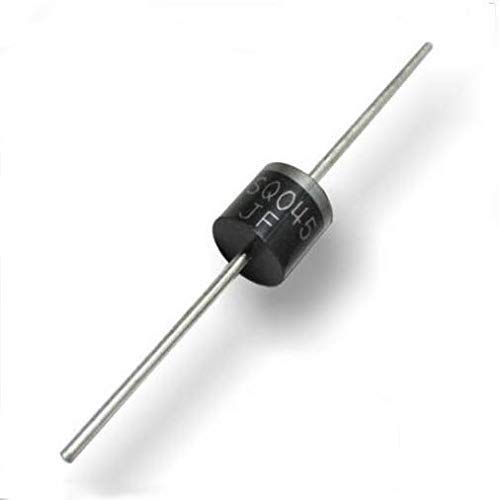
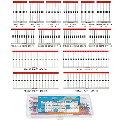
While it is possible to connect any type of diode to the back of a solar panel, the type and selection of a bypass diode depends mainly on the current and power rating of the cells, and/or panels, it has to protect.
The most common type of bypass diode used is the Schottky diode with current ratings ranging from 1 to 60 amperes and voltage ratings of up to 45 volts, which is more than enough for a single 12V or 24V battery charging solar panel.


Great insights into the importance of bypass diodes in protecting solar panels! As someone who is passionate about renewable energy, I appreciate the detailed explanation of how bypass diodes work and their benefits. It’s fascinating to learn that bypass diodes can prevent damage to solar panels caused by sudden surges in voltage. I will definitely consider this information when installing or maintaining my own solar panel system. Thanks for sharing!
Nice article! I only have 2 panels, though. I was planning to “diode-OR” each panel together, at the regulator (no battery). So if one panel isn’t producing enough voltage, the diode blocks it from drawing down the other panel.
It seems to me that a bypass diodes would only benefit series-conbected panels, as they would only conduct if a panel’s output voltage dropped below 0.3V (typical Schottky Vf), effectively “shorting out” the panel. In my case, I don’t see any benefit. Or am I missing something?
Bypass diodes connected in parallel with a pv panel prevent excessive reverse voltage damage to the panel from shading or overheating.
Blocking diodes connected in series with a pv panel prevents current (other pv panel or battery current) from feeding back through a panel during times of no or low isolation.
Thank you for the good tutorial. Are the words Anode and Cathode reversed in this statement? the diodes “Anode terminal is connected to the positive side of the cell while the diodes Cathode terminal is connected to the negative side of the cell.”
Yes thanks, it was an typing error which has been corrected 🙂
Great learning! The merchant of my 360Watt panels with 60 cells is trying to convince me that the panel has diodes build in for this purpose. I have my doubts as they are for sure invisible than and I noticed from 2 panels in series the output drops dramatically when one panel becomes shaded. Is there an easy way to actually measure the existence of build in diodes, or should I for peace of mind still add the diodes externally? For 60 cells, how many diodes in series should I use? I’ve seen junction boxes for sale with up to 6 diodes.
Appreciate your thoughts
Nowadays, most good quality photovoltaic panels already have factory installed bypass diodes incorporated into their design during manufacture, or have diodes visibly installed and soldered in the junction box as sometimes the junction box manufacturer is different from the pv panel manufacturer allowing a standard off-the-shelf junction box to be used with an assortment of different wattage pv panels.
A typical 60 cell (6×10) panel would commonly have 3 diodes in reverse paralleling across ten solar cells. Your manufactures datasheet supplied with the panels (or online) would indicate this. But as you said, externally connected Schottky diodes can also be added for peace of mind although you will need to determine the VRRM minimum value and buy diodes with a greater value. Also they may increase reverse panel losses.
This is not for publication. Your tutorial is instructive and I have been learning from it, but I noticed a lot of errors on this page that could confuse students. The diagram “Series Connected PV Cells” shows the current flowing from negative to positive. That’s what electrons do, but current is defined as opposite. The text says the maximum power point of the 3-cell series is at 1.5V, but the diagram shows it lower. I don’t know which is correct, that is, I don’t know whether a “0.5 volt photovoltaic cell” is a cell with 0.5V open circuit voltage or one with its MPP at 0.5V. The diagram “Shaded PV Cell” shows the current going retrograde from cell 3 to cell 2. I’m sure you know that in this series arrangement, the current is the same throughout the circuit. The text under that diagram says “This reverse voltage causes current to now flow in the opposite direction through the shaded cell…” In fact the current is still flowing in the forward direction, but the voltage across the cell is reversed since it is acting as a resistance without emf.
I know it’s not easy to put these things into words. You deserve credit for trying.
To answer your comments:
1. Electrical current is the rate of the flow of electrons (charge) around a circuit. The directional flow of conventional current is given by the direction in which positive charge moves, the flow of electrons is in the opposite direction. A PV cell is a current source where electrons are stimulated to flow by sunlight (photons).
2. In the basic example given of cells connected together in series, the cells 0.5 Voltage corresponds to the open circuit voltage, Voc. A typical single PV cell will have a Voc in the range of 0.5V to 0.6V The maximum power point, or MPP is a combination of current and voltage for which the cells generated output power reaches its maximum.
3. You are correct that in a series circuit the same current flows through each part of the series circuit, as it only has one path for the current to flow. When a cell (or complete panel) becomes shaded its output drops dramatically and the current output from the panel is limited by the current from the shaded cell. This is because the cell stops becoming an electrical generator and becomes a load for the other cells dissipating the power generated by the illuminated cells in the string. The pn-junction of the shaded cell is forced into reverse bias and since the shaded cell is now acting as a semiconductor resistance, the circuit current passes through its pn-junction in a reverse direction as shown.
How does it work when you parallel 2 strings of 3 cells?
Good job about solar cell protection it’s easier for student understand. Thank you
If bypass diode is fail but module ok then what is out put of module
What is the condition of fail, open-circuit or short-circuit
Nice you present a clear data it is easier for me 2 understand and thnkq