
Induction Generator
Induction Generator as a Wind Power Generator
![]()
Rotating electrical machines are commonly used in wind energy systems and most of these electrical machines can function as either a motor or a generator, depending upon its particular application. But as well as the Synchronous Generator we looked at in the previous tutorial, there is also another more popular type of 3-phase rotational machine that we can use as a wind turbine generator called an Induction Generator.
Both the synchronous generator and the Induction Generator have similar fixed stator winding arrangement which, when energised by a rotating magnetic field, produces a three-phase ( or single phase ) voltage output.
However, the rotors of the two machines are quite different with the rotor of an induction generator typically consisting of one of two types of arrangement: a “squirrel cage”, or a “wound rotor”.

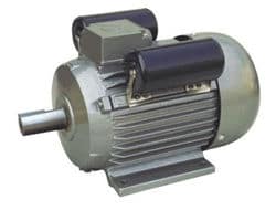
Induction Generator construction is based on the very common squirrel-cage induction motor type machine as they are cheap, reliable, and readily available in a wide range of electrical sizes from fractional horse power machines to multi-megawatt capacities making them ideal for use in both domestic and commercial renewable energy wind power applications.
Also, unlike the previous synchronous generator which has to be “synchronised” with the electrical grid before it could generate any electrical power. The induction generator can be connected directly to the utility grid and driven by the wind turbine rotor blades at variable wind speeds once it is brought on line from stand still.
For economy and reliability many wind power turbines use induction motors as generator which are driven through a mechanical gearbox to increase their speed of rotation, performance and efficiency. However, induction generators require reactive power usually provided by shunt capacitors in the individual wind turbines.
Induction machines are also known as Asynchronous Machines, that is they rotate below synchronous speed when used as a motor, and above synchronous speed when used as a generator. So when rotated faster than its normal operating or no-load speed, an induction generator produces AC electricity. Because an induction generator synchronises directly with the main utility grid – that is, produces electricity at the same frequency and voltage – no rectifiers or inverters are required.
However, the induction generator may provide the necessary power directly to the mains utility grid, but it also needs reactive power to its supply which is provided by the utility grid. Stand alone ( off-grid ) operation of the induction generator is also possible but the disadvantage here is that the generator requires additional capacitors connected to its windings for self-excitation.
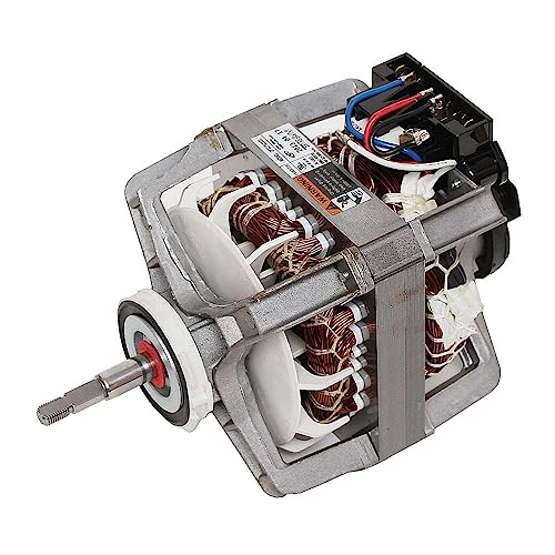
Three-phase induction machines are very well suited for wind energy and even hydroelectric generation. Induction machines, when functioning as generators, have a fixed stator and a rotational rotor the same as for the synchronous generator. However, excitation (creation of a magnetic field) of the rotor is performed differently and a typical design of the rotor is the squirrel-cage structure, where conducting bars are embedded within the rotors body and connected together at their ends by shorting rings as shown.
Induction Generator Construction

As already mentioned at the beginning one of the many advantages of the asynchronous machine is that it can be used as generator without any additional circuitry, such as an exciter or voltage controller, when it is connected to a three-phase mains supply. When an idle asynchronous generator is connected to an alternating current grid, voltage is induced into the rotor winding, similar to a transformer with the frequency of this induced voltage being equal to the frequency of the applied voltage.
As the squirrel cage rotors conducting bars are short-circuited together, a large current flows around them and a magnetic field is created inside the rotor causing the machine to rotate.
Since the rotor cage magnetic field follows the stators magnetic field, the rotor accelerates up to synchronous speed set by the frequency of the grid supply. The faster the rotor rotates, the lower is the resulting relative speed difference between the rotor cage and the rotating stator field and thus the voltage induced into its winding.
As the rotor nears synchronous speed it slows down as the weakening rotor magnetic field is insufficient to overcome the friction losses of the rotor in idle mode. The result is that the rotor is now rotating slower than synchronous speed. This means then that an induction machine can never reach its synchronous speed as to reach it there would be no current induced into the rotors squirrel cage, no magnetic field and thus no torque.
The difference in rotational speed between the stators rotating magnetic field and the rotor’s actual speed is commonly referred to in induction machines as “slip”.
Slip must exist for there to be torque at the rotor shaft. In other words, “slip”, which is a descriptive way of explain how the rotor is continually “slipping-back” from synchronisation, is the difference in speed between the stators synchronous speed, given as: ns = ƒ/P in rpm, and the rotors actual speed nR also in rpm, and which is expressed as a percentage, ( %-slip ).
Then the fractional slip s, of an induction machine is given as: 
This slip means that an induction generators operation is thus “asynchronous” (not-synchronised) and the heavier the load attached to an asynchronous generator, the higher is the resulting slip, as higher loads require stronger magnetic fields. More slip is associated with more induced voltage, more current and a stronger magnetic field.
Thus for an induction machine to operate as a motor its operating speed will always less than the rotational speed of the stator field, namely, the synchronous speed. For an induction machine to work as a generator its operating speed must be above the rated synchronous speed as shown.
Torque/Speed Characteristics of an Induction Machine

At standstill, the stators rotating magnetic field has the same rotational speed with respect to both the stator and the rotor as the frequency of the rotor and stator currents are the same, therefore at standstill slip is positive and equal to one ( s = +1 ).
At exactly synchronous speed, the difference between the rotational speed and frequency of the rotor and stator will be zero, therefore at synchronous speed no electrical energy is consumed or produced, and as such the motor’s slip is equal to zero ( s = 0 ).
If the speed of the generator is driven above this synchronous speed by external means the resultant effect will be that the rotor will rotate faster than the rotating magnetic field of the stator and the polarity of the induced rotor voltage and current is reversed.
The result is that the slip now becomes negative ( s = -1 ), and the induction machine generates current at a leading power factor back into the mains utility grid. The power transferred as an electromagnetic force from the rotor to the stator can be increased by simply rotating the rotor faster which will then result in an increase in the amount of electricity generated. The torque characteristics of an induction generator ( s = 0 to -1 ) is a reflection of the induction motor characteristics ( s = +1 to 0 ) as shown.
The speed of the induction generator will vary with the rotational force (moment, or torque) applied to it by the winds energy but it will continue to generate electricity until its rotational speed falls below idle. In practice, the difference between the rotational speed at peak generating power and at idle, (synchronous speed) is very small, only a few percent of the maximum synchronous speed.
For example, a 4-pole generator with a synchronous idle speed of 1500 rpm attached to the utility grid with a 50 Hz current, may produce its maximum generated power rotating at only 1-to-5% higher, (1515 to 1575 rpm), easily achieved using a gearbox.
This is a very useful mechanical property that the generator will increase or decrease its speed slightly if the torque varies. This means that there will be less wear and tear on the gearbox resulting in low maintenance and long service life and this is one of the most important reasons for using an Induction Generator rather than a synchronous generator on a wind turbine which is directly connected to the electrical utility grid.
Off-grid Induction Machine
We have seen above that an induction generator requires the stator to be magnetised from the utility grid before it can generate electricity. But you can also run an induction generator in a stand alone, off-grid system by supplying the necessary out-of-phase exciting or magnetising current from excitation capacitors connected across the stator terminals of the machine.
This also requires that there is some residual magnetism in the rotors iron laminations when you start the turbine. A typical circuit for a three-phase squirrel-cage induction machine for use off-grid is shown below. The excitation capacitors are shown in a star (wye) connection but can also be connected a delta (triangular) arrangement.
Capacitor Start Induction Generator

The excitation capacitors are standard motor-starting capacitors that are used to provide the required reactive power for excitation which would otherwise be supplied by the utility grid. The induction generator will self-excite using these external capacitors only if the rotor has sufficient residual magnetism.
In the self-excited mode, the generator output frequency and voltage are affected by the rotational speed, the turbine load, and the capacitance value in farads of the capacitors. Then in order for self-excitation of the generator to occur, there needs to be a minimum rotational speed for the value of capacitance used across the stator windings.
The “Self-excited induction generator”, (SEIG) is a good candidate for wind powered electric generation applications especially in variable wind speed and remote areas, because they do not need external power supply to produce the magnetic field. A three-phase induction generator can be converted into a variable speed single-phase induction generator by connecting two excitation capacitors across the three-phase windings. One of value C amount of capacitance on one phase and the other of value 2C amount of capacitance across the other phase as shown.
Single-phase Output from a 3-phase Induction Generator

By doing this the generator will run more smoothly operating nearer to unity (100%) power factor (PF). In the single-phase operation, it is possible to obtain near three phase efficiency producing approximately 80% of the machines maximum rating. However, care must be taken when converting a 3-phase supply into a single-phase supply as the single phase line-to-line voltage output will be twice that of the rated winding.
Induction generators work well with single-phase or three-phase systems that are interconnected to the utility or as a self-excited stand alone generator for small scale wind power applications allowing for variable speed operation. However, induction generators require reactive excitation to operate at full power thus they are ideally suited for interconnection to the utility grid as part of an grid-tied wind power system.
To learn more about “Induction Generators”, or obtain more wind energy information about the various wind turbine generating systems available, or to explore the advantages and disadvantages of using induction generators as part of a grid connected wind turbine system, Click Here to get your copy of one of the top three-phase Self-excited Induction Generator books direct from Amazon today.


Hello again,
I have learnt a bit more regarding the induction generator since my previous post. In fact, I find that most regarding induction generators, if not all information sites, have an assumption as to how these generators work. Then magically the energy produced is extracted. This far from reality. For example, given that my small project is running with two motors, and can be described as self-excited, I cannot produce a constant supply of electricity if I vary the speed of the prime mover, hence also the connected generator. So I am confused as to how Wind Turbines can produce energy with variable speeds: unless there is a variable gear box connected to the output drive or similar. Also, I have found that the output from a self-excited generator requires capacitive tuning to supply current to promote the magnetic fields. This requirement, if not applied, corresponding with a good power factor, will create a lot of grumpy turbulence within the generator..
All in all, unless there is some secret society that one needs to belong to for specific information, I have yet to locate a web information site that actually and in detail explains how their system(s) works and when mine will not, given the circumstances stated for producing energy. I am able to produce energy with my small system. Large systems are essentially, working on the same principal, or are they?
Have a good day.
Dwane
Hello all,
First why are wind generators connected to the grid? If you have the grid, you have power? Also, a simple solution to the magnetic activation of the “Induction Generator” is to take a feed through a diode and capacitor from the output of the generator to charge a battery that drives an inverter at 250v, for the requirement for the maintenance of the induction generator to obtain the magnetic field. When the wind has stopped, then when restart is required, inverter provides necessary magnetic field from charged battery.
The statements quoted below indicate that the author of this article is not a professional engineer. Typical wind turbine generators are induction machines, but they produce wild AC and require power electronics to convert it to constant frequency so that it can be connected to the grid. These statements should embarrass the author:
“…Also, unlike the previous synchronous generator which has to be “synchronised” with the electrical grid before it can generate power, the induction generator can be connected directly to the utility grid and driven by the turbines rotor blades at variable wind speeds…Because an induction generator synchronises directly with the main utility grid – that is, produces electricity at the same frequency and voltage – no rectifiers or inverters are required…”
Also, power electronics produce very dirty power. As the contribution of wind turbines to the electrical grid increases, this will become a serious problem and require solution.
Thank you for your observations, clearly you are much more professional than us.
Do you even know what fixed speed wind turbines are? See the Vestas V27 for example. The stator is magnetized with the grid’s frequency, so the power produced is also 50/60Hz. You are referring to variable speed turbines.
A bit of humility would do you good
Hi , instead of vertical axcel , i am trying to built horizontal axcel wind mill , i am looking for 24v stator winding and connection diagram,,, can anyone pls help.. its a permanent magnet rotar and stator design.
The induction generator which as you say is asynchronous is not able to produce 50/60Hz electricity? They do however produce ample harmonics termed in the industry as ‘dirty energy’. These harmonics which incidentally through smart meters are fraudulently added to consumers power bills are totally useless and will not boil a jug. A wind turbine cannot boil a jug. A wind farm cannot power a city. Which of course means wind turbines are a giant scam. Has anyone proven the 50/60Hz output of a wind turbine? Has anyone through tests separated the 50/60Hz from the harmonics to prove how much 50/60Hz is being generated. Your comments please.
Has someone put a [Nookleer] wind sock in your mouth? If not…
I think you need to learn about power factor, cos phi, true power, apparent power, KW, VA, oscilloscopes and Fast Fourier Transform.
Yes, I have tested the power produced by induction generator wind turbines and separated the voltage and current frequencies. The harmonics at your house’s service enterance are much worse- typically because of all of the uncorrected inductive loads and switching power supplies. Industrial wind turbines are required to be fast acting VAR and voltage controllers.
The utility companies automatically upcharge your power usage in residential areas because they know that the power factor is lousy and they have to size the infrastructure components much higher. Large facilities are charged based on usage and power factor their facility uses/influences, which incentivizes them to be responsible electricity consumers.
Wind turbines have boiled, are boiling, and will boil many jugs.
Any other questions, let me know.
beautifull answer!
How to calculate the capacitor?
Hi guys:
It looks like the diodes i have found so far are of very low capacity.and to make a bridge rectifier that can handle about about 3 kwatt rated power is not easy… What if i use a portable battery charger as a rectifier and then connect the inverter to the output of that (homemade rectifier). The battery charger is (60 AMP)and 12 V.
You can simply use multiple diodes in parallel to achieve the same general result.
Hi guys:
I got the idea that the 3 phase self excited induction generators come with a set of capacitor bank connected across the stator terminal for excitation.
My Q is : why do we need to make capacitor value evaluation to use those generators as wind turbine generators???
What would happen if we connect one to the wind turbine without any change in the capacitor bank???
Squirrel cage Induction Generators as a machine have one major disadvantage, an absense of excitation as it has no separate field circuit. The reactive power required for excitation to generate any useful output can be taken from the supply according to its power factor. However, this reactive power must usually be compensated for by shunt capacitors.
the writer seems to lack a lot of knowledge in Electricity..he is claiming that wind turbines are giant scams. It can not boil water. Asynchronous generator have little compared to synchronise generator. Infact it’s characteristics are the same. although asynchronous generator is claimed to have poor voltage regulation in standalone mode.but the fact is that all self excited generators have poor voltage regulation unless it is equipped with a voltage regulator..
Thank you for the article. It is very informative. Can you tell me, if the induction wind turbine is running and attached to the grid, and then the grid is disabled, would it continue to send power back to the grid or would it be immediately disabled?
No idea, please ask the manufacturer of your wind turbine.
I have a second question. Please excuse if it is too simple. When the Induction generator is connected to the grid on a day without wind, will the grid power it and make it turn (making it consume energy) or is the power disabled and the blades sit idle?
No, no wind, no electricity, otherwies it would act as a giant fan.
There needs to be a relay in place to cut power when not creating power. You’re basically asking if you plugged a 3-Ph motor into a 3-Ph power supply if it would run, and yes it would run!
There needs to be a relay or SRC in place to stop it from consuming power.
In California, there are small wind turbines that have the relays stuck on and they run at full speed when there is no wind because they are simply a motor being supplied with 3-Phase power; I have witnessed this with my own eyes!
directly shut down, we experienced this during a grid failure
Hi,
Interesting to read all this. I have plans for so lang now to build a little windturbine. For me it’s now just to play and experiment. When I have something little working I can go bigger. I just have one question on using a 3ph Asynchronous motor; how do I calculate what capacitors (C and 2C) I need when I want to a 1ph system. If you could be so kind to give me the formula that I need for that.
Kind regards,
Rob van den Wijngaart
Assuming a balanced three-phase machine, the 3-phase terminal voltage and currents will be 120 degs. apart from each other.
If the single-phase connected load is constant and resistive then:
i(load) = root(3) * i(cap)
where i(cap) = V(line)/Xc and Xc = 1/(2pi*f*C)
Note that the current i is the rms value of the balanced 3-phase currents, the output is about 80% of its power rating, and also 2C is double the capacitance value of C.
Another way of looking at this is:
80% of kW rating = root(3) * sqr(V(line)) * (2pi*f*C) and rearrange for C
Hello,
Great info.
I am working on a very low speed project – 30rpm. Do you have any thoughts on a direct drive pmg?
Have people build 150pole + pmg’s? If so can you point me in to the work?
Best,
Phil
Direct drive can cause variations in output due to variations in the prime mover and requires more torque, so a gearbox or belt/pulley drive would be better to drive the pmg at higher speeds, after all a 1% variation at 400rpm is a lot less than a 1% variation at 40rpm.
A 150-pole machine would be classed as a special machine possibly with high kW ratings and hence would have a very special price tag. It is better, easier and cheaper to stick with conventional off the shelf 2 or 4-pole machines and set the speed accordingly using the standard equation of: RPM = frequency*(2/number of poles)*60 and a gearbox.
ABB and Siemens do a full range of electrical machines.
As I understand it an asynchronous generator such as a wind turbine cannot produce 50/60Hz electricity. This is the first fraud
A turbine does however produce useless harmonics which through smart meters are fraudulently added to consumers power accounts. This is the second fraud
A wind turbine illegally alters the characteristics of the grid.
A turbine produces dangerously high earth voltages.
A turbine creates capacitance in the grid
I do not know how engineers have confused harmonics with useful electricity
A turbine cannot boil a jug
All wind turbines should be shut down
Brian you probably should be shut down.
Wind turbines might not be the best way to make power, but they make power nonetheless.
Brian, you are the one who’s confused. Why on earth would a turbine not boil a jug in the first place? To play along with your ignorant take on harmonics, know that a resistive heater doesn’t give a damn about harmonics. So the jug will boil.
How to find value of capacitance which?
I have been experimenting with a 20hp Baldor 9 wire 460v motor as a generator for about 6 months now. The motor is hard wired Delta. I have several layouts for capacitor connections for Wye motors but none for Delta layouts.
Could you supply one or more for me?
Another question has been that one of the layouts for wiring has a ground and a neutral taken between, on your diagram, poles 1 and 2. There are 2 coils between each leg so it would be the point those coils come together. I have been reluctant to try this as I’m concerned it would damage the generator. Any thoughts on this?
This may help, Baldor Connections.
Hi Phil,
I have the same motor you do and have tried numerous setups with reasonable success.
Regarding your first question on wiring: Although Delta layouts show two capacitors – one between Pole 1 and Pole 2, and another between Pole 2 and Pole 3. The Pole 2 was used as Neutral running to Grd. I did not have good generation from it. Also after trying the midpoint between Pole 1 and Pole 2 as the Neutral and grounding it, Pole 3 voltage doubled.
My best results are actually a Y layout with 3 capacitors. Take your 3 lines from the poles and put two wires with spade connectors on each. Line 1 wires connect to Cap1 & Cap 2. Line 2 wires connect to Cap 1 & Cap 3. Line 3 wires Connect to Cap 2 and Cap 3. You should be able to pull the full 480v (Pole to Pole or 280v Pole to ground) and around 15 amps with the right capacitors. I’d suggest starting with 40mf per leg to get you in the ballpark. I also use the same layout on the 12 wire Reliance 40hp I’m currently building as a wye generator.
Now if someone out there will come up with a Voltage Regulator for Self-Excited Induction Generators, it would make my year!
HJi research “rotoverter”. There are many options available to you as your research and hunting through “Rotoverter”. You might be surprised!
Hello,
First off, thank you for this information.
Secondly, I am looking for information/answers about what the best generator would be for uses of “off grid” high wind speed, perferably “direct drive”. Based on your information a PMSG seems like the best option but none of the information including anything about generation at high wind speed (60-80mph)
Lastly, what are the main issues/challenges with generatoring electricity at high wind speeds?
Tip speed ratio, turbulence, self destruction due to high tip speed, etc.
How to get generator 12 pol geve me circit diagram and diameter wird
Thanks
Hi. If I wanted to convert a Variable Speed Pitch Regulated Wind turbine into a Fixed Speed Stall Regulated turbine, What main components would need changing and how and why?
Disable the mechanism which adjusts the blades and fix them at the angle you need.
Hello! this is cool! Induction generators use squirrel cage rotors and need excitation to produce a voltage.